


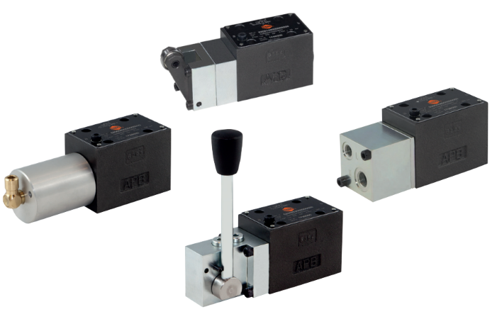
S6N, S6Y, S6R, S6H series Directional Control Valve
Directional control valve size 6, mechanically/ hydraulically/ pneumatically controlled
- Hole pattern to DIN 24340 and ISO 4401 or line connection G3/8
- Female thread in valve body
- 5 chamber design
- No dynamic seals
- Actuation types: pneumatic hydraulic roller lever hand lever
- Valves generally with FKM seals
Features & Benefits
- Hole pattern to DIN 24340 and ISO 4401 or line connection G3/8
- Female thread in valve body
- 5 chamber design
- No dynamic seals
- Actuation types: pneumatic hydraulic roller lever hand lever
- Valves generally with FKM seals
Technical Information
Medium: HLP, oil purity class according to ISO 4406: 20/18/15, other process liquids upon request
Operation: spool valve, directly operated
Actuation method: proportional solenoid
Mounting type: Flange
Line connection: subplate or female thread in valve body
Nominal size: 6
Operating pressure:
connection P, A & B: 350 pressure (br) max.
Port T:
pneumatic N: upto 100
hydraulic Y: up to 160
roller lever R: upto 20
hand lever H: upto 160
Control pressure range P: pneum. N P[bar]: 4 to 10
hydr. Y P[bar]: 5 to 315
min control pressure P = 2.5bar, if port T depressurized
Control volume V:
- pneum. N Vst[cm3]: 1.6
- hydr. Y Vst[cm3]: 0.5
Switching times te/ta:
pneumatic N: depending on control air flow
hydraulic Y: depending on control oil flow
roller lever R: depending on control element
Operating force:
roller lever R:
- Fb (0 bar) = 70N
- Fb (20bar) = 130N
hand lever H: Fb ca. 35N
Installation position: preferably horizontal
Viscosity: 12...500mm2/s
Flow Qmax:
actuation
N 00 & Y 00: see characteristics
R 00: 80l/mion
H 00: 80l/min
MTTFd: hydraulic components with np>=1000000 cycles per year: 150 years
Fluid temperatures: 0...+70degC
Ambient temperature: -20...+50degC
Circuit diagram: according to DIN 24340 and ISO 4401 (CETOP03)
Materials:
Housing: cast iron
piston slide valve: hardened steel
seal: FKM
pneumatic actuation: aluminum, brass
hydraulic a ctuation: steel
roller lever: steel, cast
hand lever: steel
thread: steel